MEMRR HO Layout
Johnson City Railroad Experience – MEMRR HO layout description
Previous Layout at ETSU
Our previous layout, which was a single plane rectangle racetrack, that had room inside the layout for assembling trains and switching activities. We had approximately 2.1 scale miles of trackage in this layout. That layout provided a good platform since 2007 for our members to use their existing individually owned modules and assemble them to create a solid modeling platform. That layout had several modules of exceptional quality and detailed scenery which we have included in our new arrangement.
One of these modules is the bridge and valley arrangement created by Dr. Fred Alsop, that is inspired by the area north of Gate City known as “Copper Creek” which has dual bridges; one for the CSX and one for the Norfolk Southern.
New Layout at JCRE
The goal was to represent parts of what is found in this area serviced by the CSX (Clinchfield) and the Norfolk Southern (Southern) railways in upper East Tennessee and Virginia. The new layout will result in 4.1 scale miles of track to operate.
The new layout has been configured to a standard of 32” radius mainlines and double track mainlines that outline the perimeter of the layout. We have also created grades and elevated track so that we are not a single plane operation. In addition, we had the criteria that the layout will support future operating sessions with multiple businesses around the layout. The branch line was installed to create a single-track loop operation that we could automate in the future for unassisted operations. Our previous staging yard has been converted with a loop back and a through yard to allow our members a way to park their trains, do other activities and then return to the layout without handling their equipment.
Less than half of the original layout tables were able to be used and all but a very few required significant modification. We have been working on this project since January 2024 and have completed phase 1 of a three-phase project. So not only will you be able to enjoy the operation of the trains, you will also be treated to watching how we create the scenery and the appearances of the other two phases.
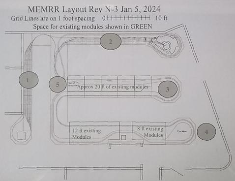
The drawing that we used to construct this layout has been labeled with five circled numbers which are described below:
1. STAGING YARD
This area is for club members to assemble and configure their trains prior to going onto the layout. These tables were our old staging yard that was in the middle of the layout. The other function for this through yard area is to be able to serve as a secondary yard for club activities requiring pickup and drop-off of rolling stock.
2. Phase 3 - MAIN YARD
This area is for the roundhouse which stores locomotives to operate in proximity to the main yard where most of the clubs rolling stock will be stored. This storage area permits the functioning of the railroad by linking mainline operation to customers to permit the cargo to reach its destination on the layout.
3. Phase 1 - Middle leg
This area is the phase 1 completion target with the existing modules widened by 18 inches to permit track to navigate both sides of the table separated by a divider. We have two themes to this operation with the upper side modeled as the fictional city of Rogersville (Named in memory of Roger Teinert). The lower side is modeled after a typical rural mountain city common to the Appalachian area. The end of the module depicts a mountain location with the branch line climbing in back of the city to transition from the city to the rural area. The branch line will traverse to the backbone area where it will connect to the lower leg and a return loop. The goal of the rural side of the layout is to depict more remote areas of a railroad operation and give visual stimulation to the viewer.
4. Phase 2 - Lower leg
This area is the second phase of the operation which utilizes a couple of our more memorable modules. The showpiece of the layout, Dr Alsop’s creation, is the cornerstone which will require some modification to accommodate tracks on both sides of the module. The end piece of this leg will depict another more modern mountain containing an operating coal mine. This module will be where the branch line makes a return loop to change direction and route back to the area shown by 3.
5. BackBone
This area is called the “backbone” and will evolve as the layout grows. In this initial stage everything on it is temporary to accommodate operation and construction for the next phase by allowing minimal disruption to the tracks and operation. This section will probably be one of the last areas to get full scenery and buildings. This section contains multiple overpasses and bridges to create more visual enjoyment. This location is called the backbone because it connects all of the legs to each other.
Area 1
Staging Yard
This area is for club members to assemble and configure their trains prior to going onto the layout. These tables were repurposed from our old staging yard that was in the middle of the former ETSU layout. The secondary function for this through yard area is for club switching activities requiring pickup and drop-off of various types of rolling stock.
Area 2
Phase 3 – Main Yard
This area includes the roundhouse which stores locomotives to operate in proximity to the main yard where most of the clubs rolling stock will be stored. This storage area permits the functioning of the railroad by linking mainline operation to customers to permit the cargo to reach its destination on the layout.
Area 3
Phase 1 - Middle Leg
This area is the first phase completion target with the existing modules widened by 18 inches to permit track to navigate both sides of the table separated by a divider.
We have two themes to this operation:
1. The upper side is modeled as the fictional city of Rogersville (named in memory of Roger Teinert).
2. The lower side is modeled after a typical rural mountain city common to the Appalachian area.
The end of the module depicts a mountain location with the branch line climbing in back of the city to transition from the city to the rural area. The branch line will traverse to the backbone area where it will connect to the lower leg and a return loop. The goal of the rural side of the layout is to depict the remote areas of a railroad operation and give visual stimulation to the viewer.
Area 4
Phase 2 - Lower Leg
This area is the second phase of the buildout which utilizes a couple of our more memorable modules. The showpiece of the layout, Dr Fred Alsop III’s creation, is the cornerstone which will require some modification to accommodate tracks on both sides of the module. The end piece of this leg will depict another more modern mountain containing an operating coal mine. This module will be where the branch line makes a return loop to change direction and route back to the middle leg of the layout.
Area 5
BackBone
This area, called the “backbone”, will evolve as the layout grows. It is called the backbone because it connects all of the legs to each other.
In this initial stage, everything on it is temporary to accommodate operation and construction for the next phase by allowing minimal disruption to the tracks and operation.
This section will probably be one of the last areas to be fully completed with scenery and buildings.
This section will also contain multiple overpasses and bridges to create more visual enjoyment.